

|
|
|
|
| Inherent Design Errors |
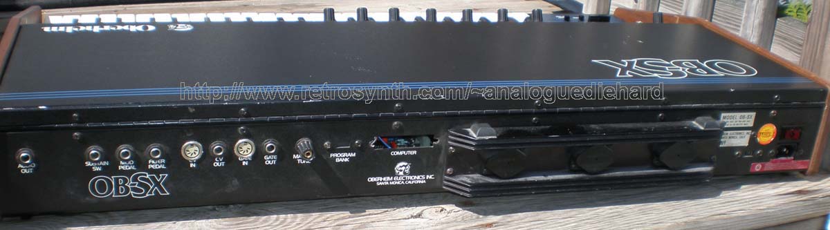
How to restore an OB-SX |
Correct Voicecard Calibration Procedure |
How Does It Sound? |
Features |
OB-SX Preset Names |
OB Model comparisions |
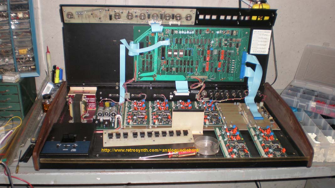
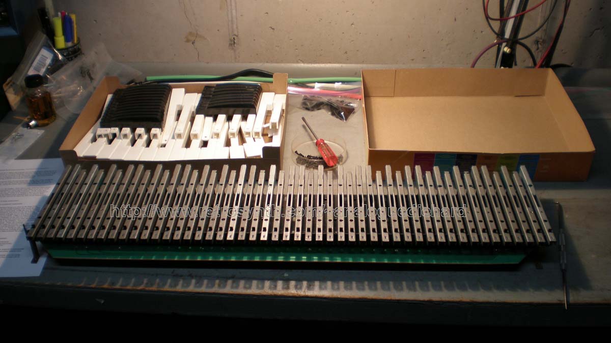
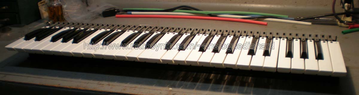
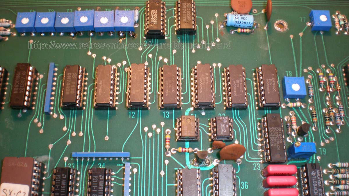
| The
patient on the operating
table (no, the KEYBOARD silly!) |
The
pile of replaced components (!!!) |
 |
 |
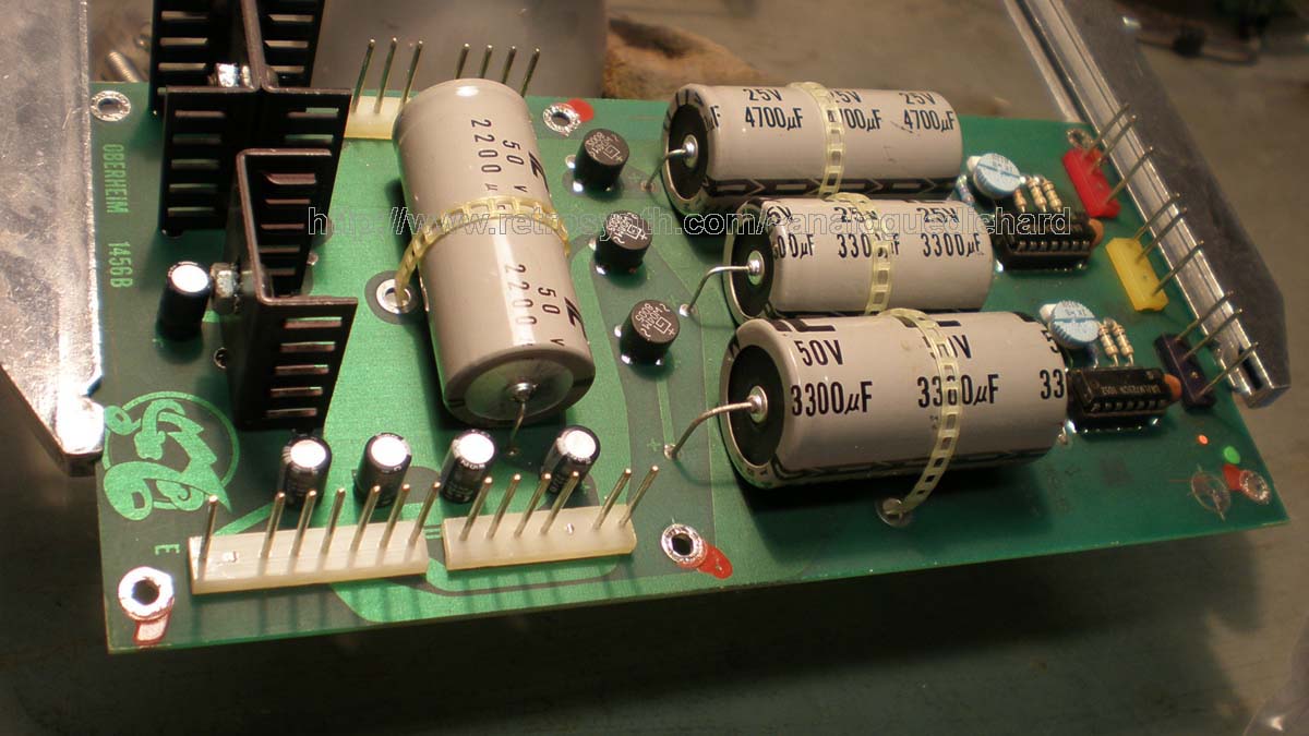
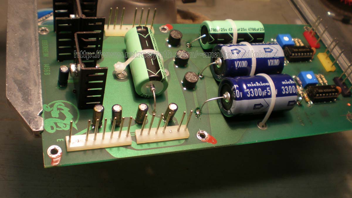
| Power
Supply before |
Power
Supply after |
 |
 |
| Just
Testing |
Final
#1 |
Final
#2 |
 |
 |
 |
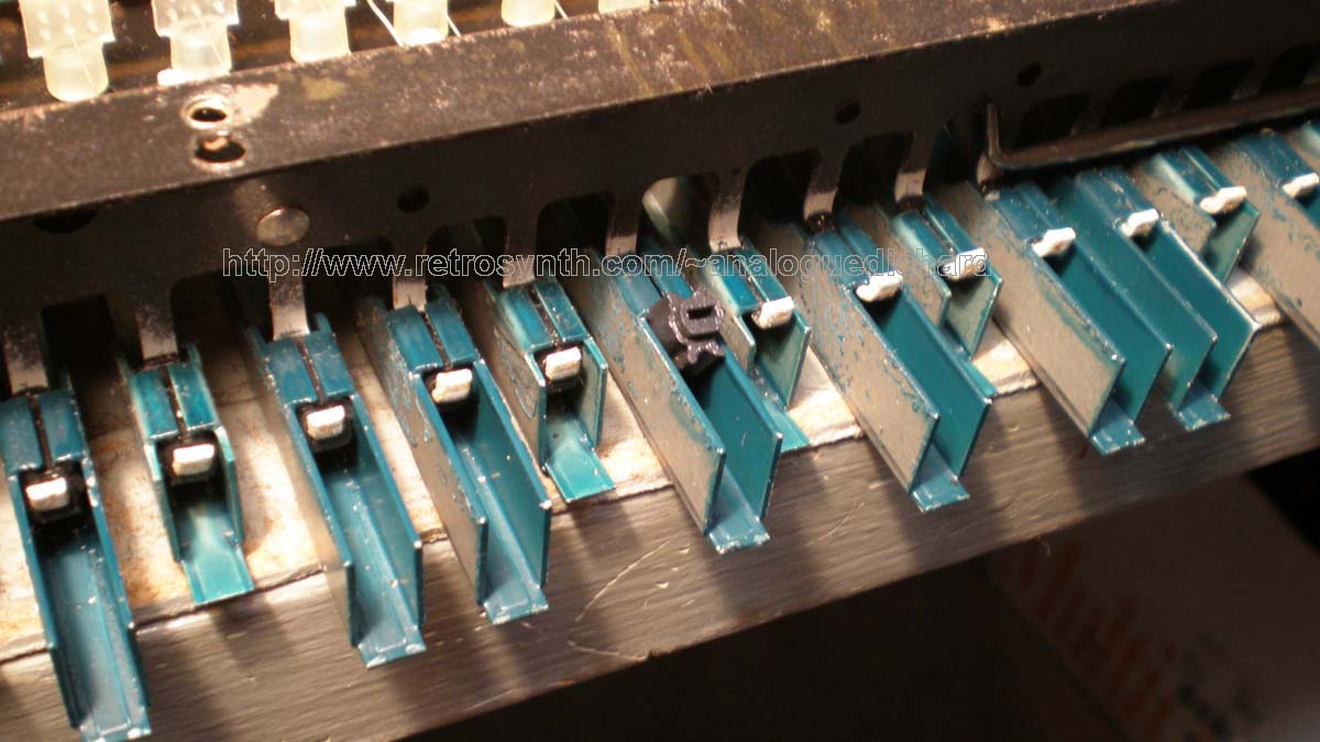
| Keyboard
assembly before new
bushings |
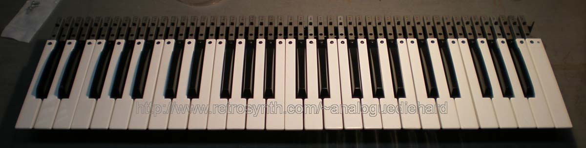
Keyboard
disassembled |
Cleaning
keyshells |
 |
 |
 |
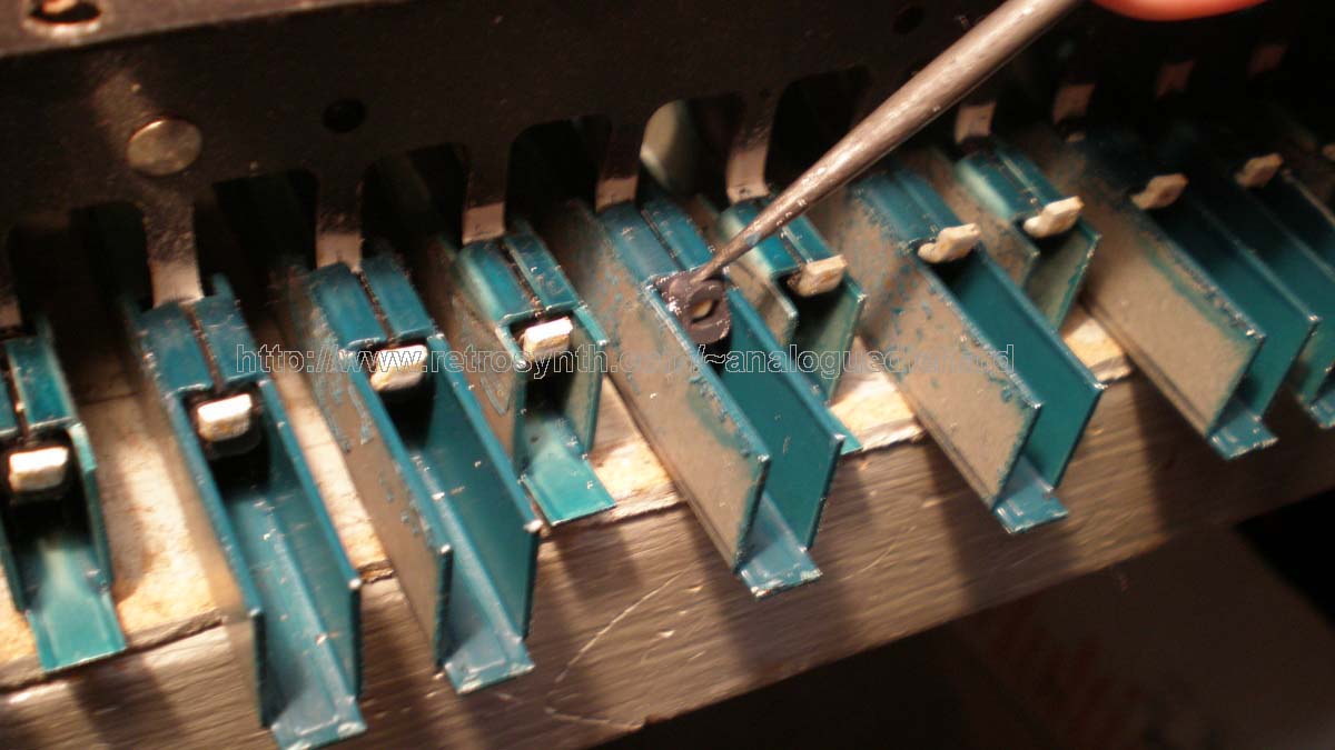
| Bushing
partially removed |
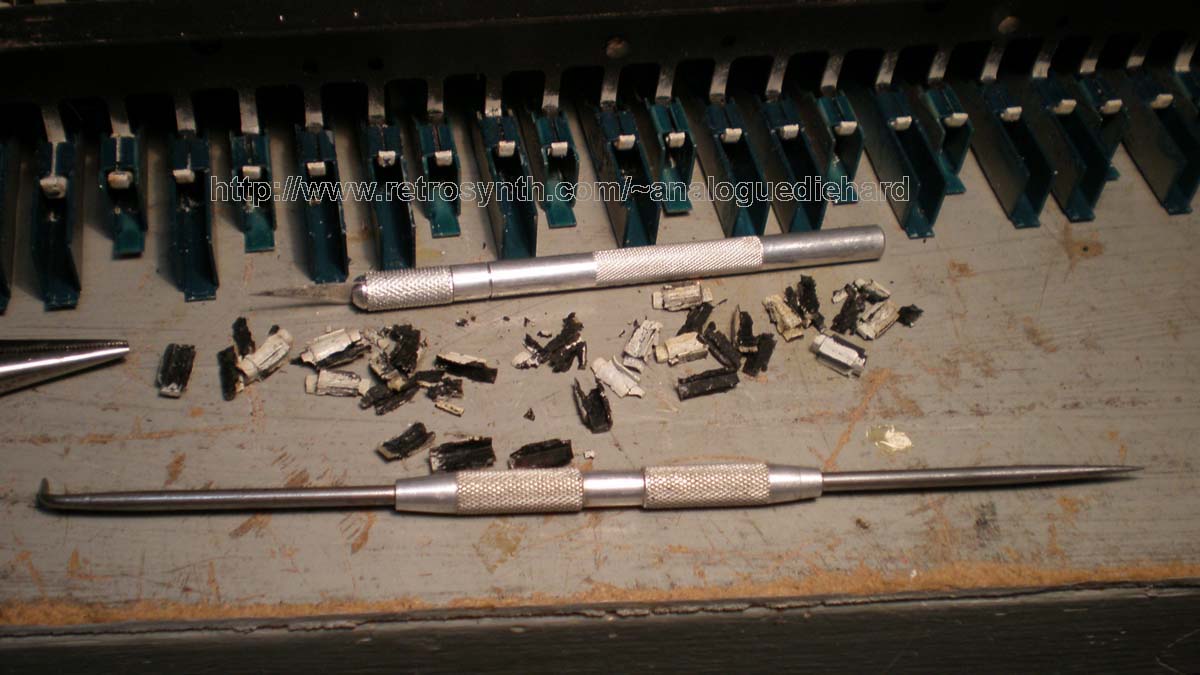
Tool
to remove bushing |
Most
bushings disintegrate upon
removal |
 |
 |
 |
| Keyboard
assembly after new bushings |
|
 |
 |
 |
 |
 |
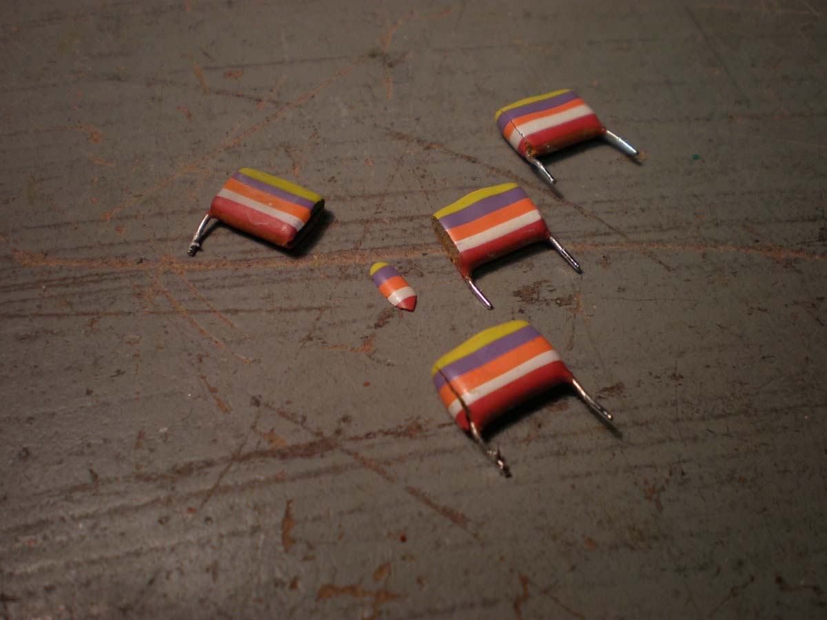
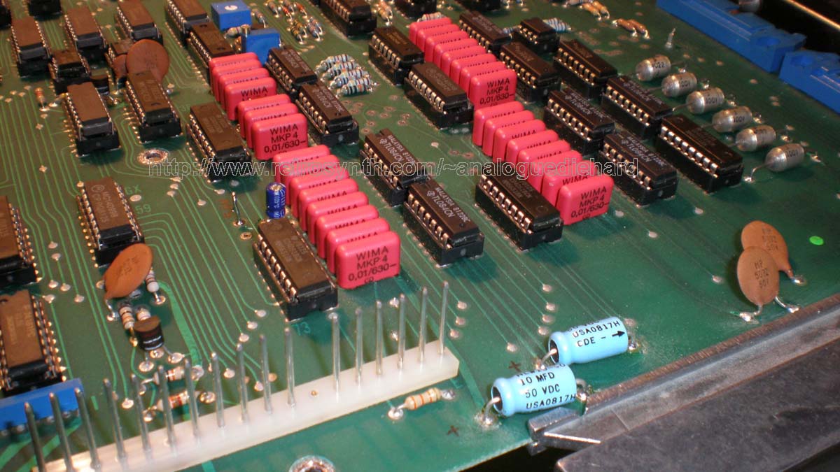
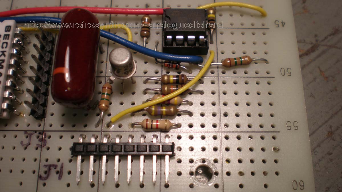
| Bad
S&H caps |
Broken
ceramic caps |
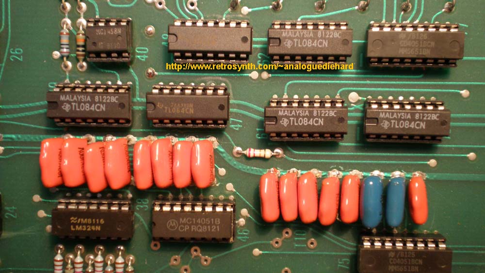
New
trimpots and electrolytic caps |
New
S&H caps |
 |
 |
 |
 |
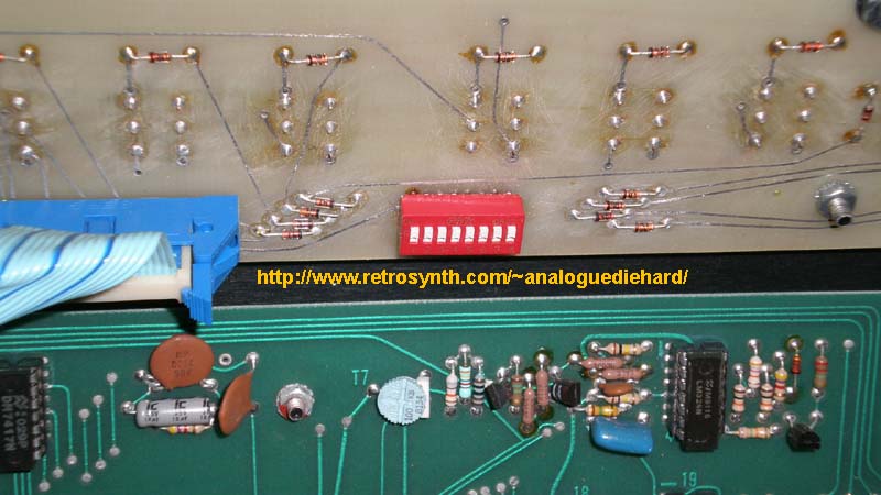
| Utility
Board |
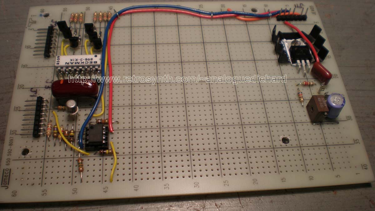
New
(+)5VDC Regulator circuit |
Utility
Board installed above Power Supply |
 |
 |
 |
| Logic Signal |
Voicecard Connector Pin |
Controller Board IC & pin # |
Bank/Program # |
| SYNC=1 (15VDC) |
D7 |
B1 |
|
| SYNC=0 |
D7 |
AC1 |
|
| WAVE1=0 (RAMP) |
D3 |
B1 |
|
| WAVE1=1 (15VDC, PULSE) | D3 |
A2 |
|
| PWM=1 |
A13 pin 2 |
C8 |
|
| PWM=0 |
A13 pin 2 |
BC3 |
|
| WAVE2=0 (RAMP) |
D4 |
B1 |
|
| WAVE2=1 (15VDC, PULSE) | D4 |
A2 |
|
| PWM2=1 |
A13 pin 5 |
BC3 |
|
| PWM2=0 |
A13 pin 5 |
BC7 |
|
| VCO2L=1 (15VDC) | D6 |
A5 |
|
| VCO2L=0 |
D6 |
B1 |
|
| CMOD=1 (15VDC) | B2 |
ABC2 |
|
| CMOD=0 |
B2 |
AC1 |
|
| TRACK=1 (15VDC) | D2 |
AC1 |
|
| TRACK=0 |
D2 |
B1 |
|
| FILMOD=1 |
A12 pin 5 |
AC8 |
|
| FILMOD=0 |
A12 pin5 |
AC7 |
|
| FM1=1 |
A12 pin 15 |
B6 |
|
| FM1=0 |
A12 pin 15 |
B1 |
|
| FM2=1 |
A12 pin 2 |
BC1 |
|
| FM2=0 |
A12 pin 2 |
B1 |
|
| LW2=1 (LFO square) |
A12 pin 12 |
BC1 |
|
| LW2=0 (LFO triangle) |
A12 pin 12 |
BC3 |
|
| PW1=5VDC (VCO1 off) |
tbd |
tbd |
tbd |
| PW1=not 5VDC (VCO1 on) |
tbd |
tbd |
tbd |
| PW2=5VDC (VCO2 off) |
tbd |
tbd |
tbd |
| PW2=not 5VDC (VCO2 on) |
tbd |
tbd |
tbd |

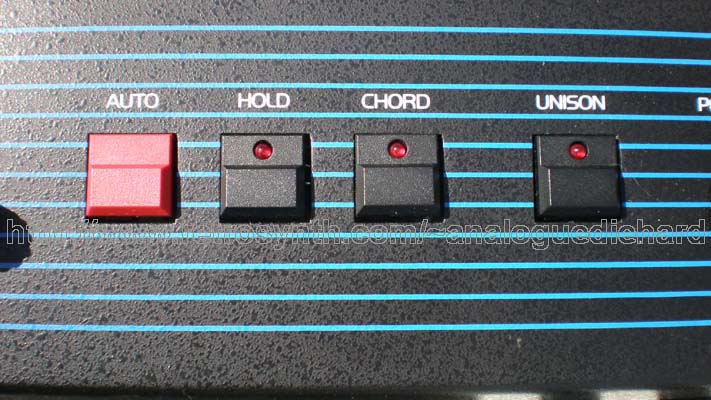
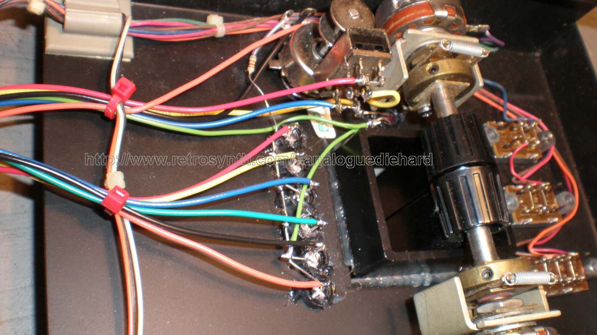
| Modified
Left Hand Control Panel |
Voice
Gate LED Driver |
Vibrato
LFO circuit |
Wiring
under LH Panel |
 |
 |
 |
 |
| BANK |
PGM #1 |
PGM #2 | PGM #3 | PGM #4 | PGM #5 | PGM #6 | PGM #7 | PGM #8 |
| A |
Brass
Ensemble |
Clavinet |
Low Strings |
Electric
Piano |
Percussive
Organ |
Flutes |
Harpsichord |
Lead Sync |
| B |
Classic Horns |
Celeste |
High Strings |
Brass in
Fifths |
Pipe Organ |
OB-SX Choir |
Harp |
Calliope |
| C |
Trumpets |
Pop Organ |
Slow Strings |
Rezz Sweep |
Combo Organ |
SX-6 |
SX-7 |
SX-8 |
| AB (48/56
only) |
Calculator |
Mellow Wow |
Fiddle |
Reed Piano |
Double Reed |
Sax |
Marimba |
PW Rezz |
| AC (48/56 only) | Ensemble
Trumpets |
Polyphonic
Portamento |
Strings |
Accordian |
Filter Drone |
Pulse Comp |
Steel Drums |
Water Wiggle |
| BC (48/56 only) | Square Wave
Mod |
Bells |
Strings II |
Sitar |
Unison
Portamento |
Cross Mod
Delay |
Kalimba |
Solo Unison |
| ABC (56 only) | Bass |
Cross Mod
Bells |
Solo Strings |
Harmonica |
Rotary Organ |
Clarinet |
Conga |
Rush Rezz |
| OB-X |
OB-SX |
OB-Xa |
OB-8 | |
| VOICE CARD |
4-8 |
4-6 |
4, 6, 8
(even only) |
8 |
|
VCOs
|
2x discrete |
2x CEM3340 |
2x CEM3340 |
2x CEM3340 |
|
Modulation
|
XMOD |
XMOD |
VCO2 FM by
VCF EG |
expanded in
software matrix |
|
PWM
|
yes |
yes |
yes |
yes |
|
VCF (lowpass only)
|
Discrete
cascaded OTAs, 12dB |
CEM3320, 12dB |
2x CEM3320,
12dB or 24dB |
1x CEM3320, 12dB or 24dB |
|
VCA
|
3080 OTA +
TL081 buffer |
3080 OTA + TL081 buffer | 2x 3080 OTA + TL081 buffer | CEM3360 |
|
Voice volume control
|
no |
no |
yes |
yes |
|
EG
|
2x CEM3310
VCF & VCA |
2x CEM3310 VCF & VCA | 2x CEM3310 VCF & VCA | 2x CEM3310 VCF & VCA |
|
LFO
|
one |
one |
two (for
dual timbrality split/layer) |
two
(software) |
|
Noise Source
|
yes |
no |
yes |
yes |
| SYSTEM |
||||
|
# of patches
|
32 |
24/48/56
depending on version |
32/120
depending on version |
120 |
|
Editing
|
Full |
Limited |
Full |
Full |
|
User Storage
|
yes |
no |
yes |
yes |
|
Timbrality
|
mono |
mono |
dual |
dual |
|
Audio Field
|
stereo |
mono |
stereo |
stereo |
|
Voicecard Audio Summing
|
3080 OTA + TL081 buffer | 3080 OTA + TL081 buffer | CEM3360 |
CEM3360 |
|
DAC Resolution
|
10 |
10 |
12 |
14 |
|
MIDI Retrofit
|
Encore
Electronics |
ElectronGate
MKC-1 |
Encore Electronics | Encore Electronics |
