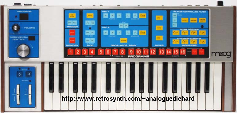
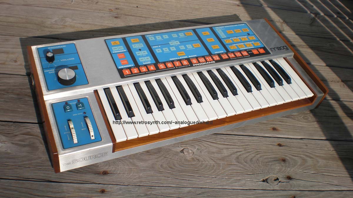
The Moog Source (its official product name was "The Source") was
designed as a programmable Minimoog,
released in
1980. It was the first product from (1970s Norlin) Moog Music to
incorporate microprocessor control (the Z-80) and also one of the first
synthesizers to replace the panel full of knobs with a touch membrane
panel and a data wheel. I have been a happy Source owner since
1985. During the analog revival of 1990-2000, this
instrument was largely ignored and undervalued because it lacked a
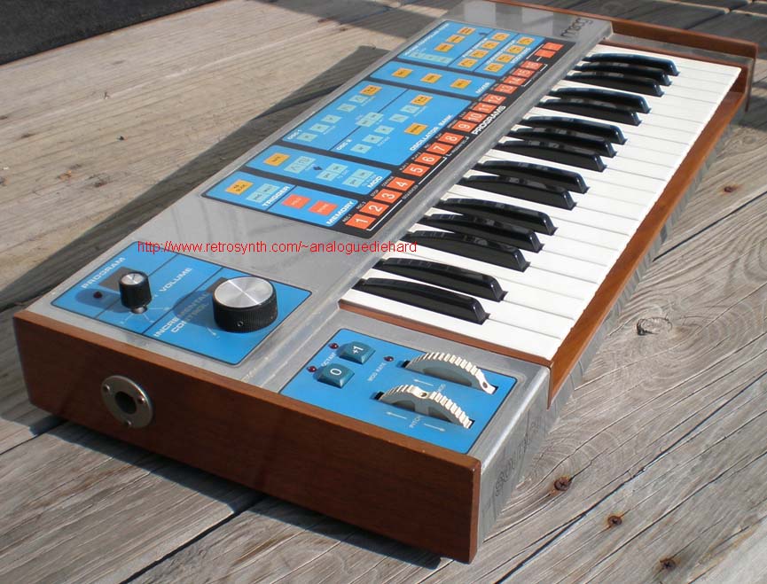
panel of knobs and switches. Fashion wise it was a bit gaudy with
its brushed aluminum case framing black bordered blue membrane panels
peppered with gold, light blue, and red buttons. But the orange
program buttons? Someone at Moog
R&D let their kids loose with the crayons. Walnut trim
complimented the aluminum case nicely although they did work loose as
they aged. And it was a lot lighter and more compact.
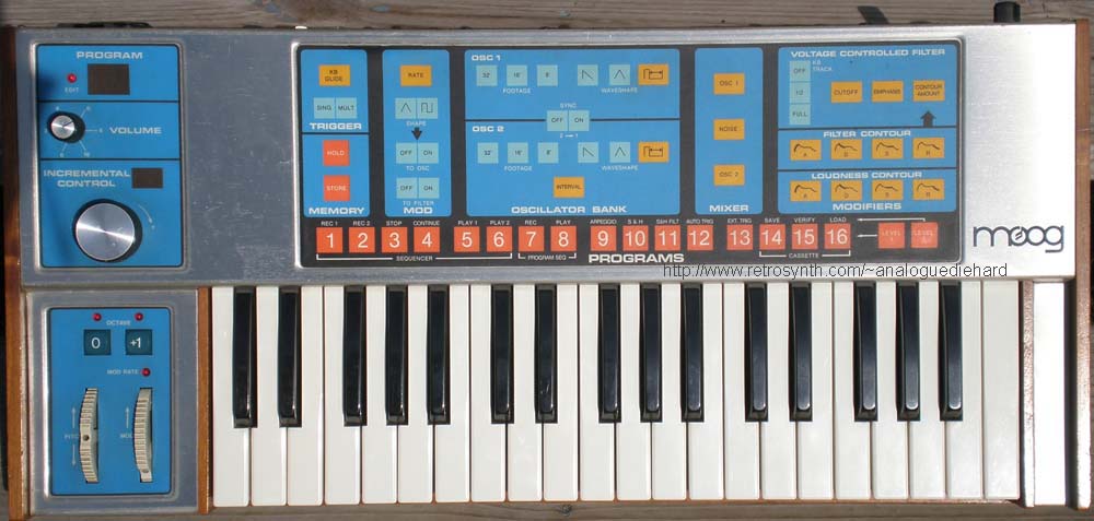
So... where's the
knobs?
Above the left hand pitch bend and
modulation wheels is a large data
wheel for editing the sound. To edit the sound, you selected
the parameter on the right hand panel which displayed the
current setting in the small LED display, and moving the data wheel
changed that setting up or down. The data wheel is
pleasantly weighted - it spins freely on a ball bearing shaft, and
because the weight provided inertia to the wheel you can whip it back
and forth with ease. This makes an
excellent controller for filter cutoff wankers. The data wheel is
basically a primitive rotary encoder, with an obviously in-house
factory designed radial transparent ring with alternating stepped black
stripes
interrupting the light beams on a pair of optocouplers. Basically
a quadrature
position and direction encoder. The Source is an adequate
application for a data controller/parameter select interface because of
the
low count of patch parameters - I always felt that the same interface
applied to complex polyphonic systems with high parameter count was too
cumbersome and unwieldy. Close on the heels of the Source was the
ARP (later
Rhodes) Chroma with a similar interface, and indeed the common
complaint was too many parameters for a data controller interface (and
the Chroma had a slidepot data controller not a wheel). And any
data controller is far better than a pair of up/down
buttons.
Many people worry about the membrane panel wearing out. I can
tell you that I have not had a single problem with mine. What can
happen is that people push the buttons with their fingernails and those
sharp nails WILL cut through the membrane surface and damage it.
So the secret is use your FINGERTIPS not your finger nails. top
Features
While it omitted some features of the Minimoog, the presence of a
microprocessor permitted some useful additions. Two 88 note
sequencers, a 24 note arpeggiator, a program sequencer, and a patch
archive cassette tape interface have been added. The sequencer is
a real
time (not step) sequencer that records note duration and interval
between notes. Using the "page 2" functions, you just press REC1
or REC2, start playing, press STOP then press PLAY1 or PLAY2 to play it
back. The sequencer clock is driven by the LFO rate.
According to the
manual, you could use the program seqeuncer to assign different patches
to any sequence event. The arpeggiator is very easy to use - when
it is activated, you simply play any pattern up to 24 notes (although
if you play C-E-E-E-G-C, the arpeggiator plays back C-E-G-C and doesn't
repeat the triple E pattern). The
arpeggiator is driven from the LFO so varying the LFO rate varies the
rate the arpeggiated notes are played back. Your input pattern
must be such that the first and last notes are the same as this defines
the repeat point, and when you press that last note the arpeggiator
immediately starts playing. While the
arpeggiator is active, you can change patches and tweak the sound in
real time - but if you slip and touch a key, the arpeggiator stops
because it "thinks" you are entering another pattern.
The orange PROGRAM buttons give you a whopping 16 locations to store
your patches (hey it wasn't bad for 1980). The large LED displays
the current program number. The buttons also perform double duty
as "page 2" - you access them by press the LEVEL 2 button on the far
right. The legends printed above the PROGRAM buttons are the
"page 2" functions.
The third
oscillator of the Minimoog was replaced with a simple
triangle/square/S&H LFO
routable to VCO and/or VCF, but the LFO would only go up to 100hz which
limited the special effects that were popular on the Minimoog (you
can't get clangorous audio FM on the filter or VCO cross modulation
effects).
The keyboard was shortened from 44 note F-to-C to 37 note C-to-C
although the keyboard mechanism is more reliable (of all my Moogs, it's
the most reliable) and the left hand
panel has octave buttons that raise or lower the keyboard range by an
octave. Below the octave buttons are the pitch bend and
modulation wheels.
Both
oscillators sport triangle, ramp, and variable 5% to 95% pulse
waveforms (the minimoog did not have variable pulse waveforms, only
fixed 50%
35% and 15% pulse) and footages of 32', 16', and 8' while the detune
control of VCO#2 had a two octave range pushing it into 2'
territory. Missing is the Minimoog "tri/ramp" combination
waveform. Variable pulse width is a very useful addition, but
it's a shame they didn't include pulse width modulation from the
LFO. VCO#2 can be hard synced to VCO#1, and when hard sync
is active the pitch bend wheel is converted to bend OSC#2 only - one of
the best features as the hard sync on this beast SCREAMS. Unfortunately you
can't route the filter EG to the hard sync'd oscillator like you can on
the Moog Rogue or Memorymoog. When
tweaking the detune, the data wheel has a finer resolution for easy
tuning. The beating between closely detuned VCOs
has that classic Minimoog sweeping sound and the VCOs do not
lock. Both VCOs have temperature compensation for stable tuning,
and my unit has been very stable all these years. The Source
includes the obligatory glide processor which is
essential for that Minimoog sound.
A mixer for varying levels of both VCOs and pink noise provides the
option to
overdrive the filter, a desireable trait from the Minimoog. Pink
noise unfortunately isn't all that useful with the limited modulation
options of the Source. Since I relegated my unit to bass duties,
I modified it so that the NOISE control actually adds audio rate FM to
the filter via VCO#2 which is a very useful modulation for bass sounds.
There is a master VCO2 scale "soft-trim" in
the mixer that trims the volts per octave scale for VCO#2. If you
want the detuning of all your patches to be the consistent between
sessions, this is a good practice when you turn the synth on.
Allow a five minute warmup before making this adjustment. I
usually have a "tuning" patch with both oscillators tuned to known
unison after a calibration. When I call up this patch it has only
one oscillator firing so I can adjust the master tune on the rear panel
to a reference, then I can quickly bring in the second oscillator using
the mixer and verify the scaling. Before making the scale
adjustment the mixer must have both VCOs audible. This
"soft-trim" is activated by holding down the STORE button and pressing
the OSC 2 button. Then while holding
high C you adjust the data wheel until the two oscillators are in
tune. The reason you use high C is this is the range that is
affected by the "soft-trim". In my experience with my unit I have
had to touch up scaling every time I turn the Source on because the
internal trimpots (there are SCALE trimpots for each VCO on the PC
board in addition to the master VCO2 scale "soft-trim") don't always
retain their position. If you cannot get the oscillators in
unison using the master scale "soft-trim" then your Source needs to be
calibrated. Make sure your tech understands this scaling system. top
Moving on to the filter, this is the classic 24dB/oct lowpass ladder
filter
made famous by the Minimoog. You can adjust cutoff frequency,
resonance, EG amount (no negative sweeps), although keyboard tracking
is limited to fixed none/half/full. The filter can self-oscillate
into a sine wave, and when keyboard tracking is set to full the
frequency of the sine wave can track the keyboard and the data wheel
has finer resolution for tuning the sine wave to pitch. This
particular filter has
better resonant colors than the Minimoog. Creamy Minimoog lead
sounds and fat basses are easy to get - the bass sounds have a little
more bottom end with that classic Minimoog midrange girth.
Between the colorful filter resonance and variable pulse width on the
oscillators, the Source is an excellent bass synthesizer capable of a
bigger variety of sounds than the Minimoog, and it serves quite well as
a "poor man's Taurus" in that you can get real close (not quite) to the
classic Taurus pedal preset that was popular on the Taurus I bass pedal
synthesizer. However there is no external audio input for the
filter and there are some Minimoog sounds not possible on the
Source. Spoinky basses - patches with filter resonance turned up
while
the filter cutoff is spiked with an EG with fast decay to zero sustain
- aren't quite the
same on the Source because the resonance on the Minimoog filter is
nonlinear. "Nonlinear" means the resonance on a Minimoog filter
does not stay constant across the full frequency cutoff range - it
disappears as the filter cutoff falls to low frequencies. So when
a "spoinky" bass is dialed up on a Minimoog, the filter resonance
disappears as the EQ sweeps the filter toward low cutoff - the net
effect is the bass sound is full sounding.
Moog subsequently viewed this nonlinear resonance as an engineering
"fault" and corrected it in new designs - including the Source.
So the resonance on the Source filter stays constant across its full
cutoff frequency range and the engineers were happy. But this was
also why later Moog instruments also didn't sound like a Minimoog and
the customers were not happy. Moog went through a lot of head
scratching to find out why and never realized that their "correction"
was the source of the difference.
Another elusive Minimoog sound is that "growl" on certain filter
cutoffs - the only keyboard in my arsenal that duplicated that "growl"
was my Moog
Voyager.
The Source has a dedicated envelope generator for the filter and
another for the VCA. They are full ADSR envelope generators - no
more "shared" decay/release control like the Minimoog.
Musicians had to wait ten long years for Moog to progress to this
system - the "shared" D/R was propogated through the Micromoog,
Multimoog,
Polymoog, Taurus I, Liberation, Prodigy, Rogue, and Taurus II.
There is a popular myth that the EGs are digital - in actuality they
are analog (technical dissection of the circuit is below).
One
nice addition thanks to microprocessor control is the EGs can be single
or multiple trigger, the latter being essential for bass sounds.
You can also use the LFO to trigger the EGs. The EGs on the
Source have a nice fast snappy attack - the range of transient times
are 3 milliseconds to 10 seconds.
To store your patch, you press the HOLD button on the left side.
This freezes the panel so no further edits can be made, and it makes
the STORE button active (two decimal points will light up in the LED
display). In HOLD mode you can also do a compare by pressing any
of the PROGRAM buttons - while holding the button down the patch in
that position is active, when you release the button it snaps back to
the edited patch waiting to be stored. When you are ready to save
the patch, hold down the STORE button then press the appropriate
PROGRAM
button where the patch is to be saved. This convention prevents
accidental patch overwrites from an inadvertant press of the STORE
button
But don't be dismayed because it doesn't sound like a Minimoog - the
Source is an excellent instrument. Only recently is the Source
getting its recognition as a respectable synthesizer - thanks to its
filter - and market prices are beginning to reflect that.
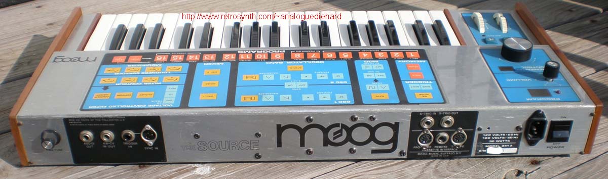
Rear panel interfacing included CV input and output, and S-trigger
input and output. "S-trigger" means the EGs are triggered with a
short to ground, "V-trigger" or voltage trigger means the EGs are
triggered with a voltage. Synthesizers never have a standard
trigger system (and still don't), and to further confuse the market
some voltage triggers use +5 volts, some use +9 volts, some use +12
volts... If you're trying to drive the Source from a
voltage trigger system like an external sequencer, you will need a
V-trigger to S-trigger conversion circuit which can be found
online. Gone but not missed on the Source are the awkward
cinch-jones sockets for S-trigger, now replaced by more convenient 1/4"
jacks. top
Modifications
and Factory Service Bulletins
I made a few modifications to my Source over the years - some
are
custom and some are for fixing known problems. One annoying
feature is
that when you power on the Source, the OCTAVE button defaults to
+1. Since I was using it as a bass synthesizer, I added a capacitor
across
the "OCTAVE 0" button, which changed it so it defaults to "OCTAVE 0" on
power up. This works because when the machine is off, the voltage
across the cap drops to near zero essentially shorting the contacts of
the button. When the power is turned on, the voltage on the cap
charges slow enough for the microprocessor to detect that the "OCTAVE
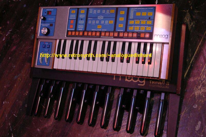
0" button contacts are closed. Another cool modification is
modifying
the Taurus II controller to control the Source remotely, described in
factory service bulletin #853B (scans of page 1, page 2, and page 3).
The Taurus II controller is
strictly a
bass pedal controller only with no internal synthesizer circuitry - it
has CV and trigger
outputs only. The reason I did this was when I routed the Taurus
II
control outputs to the CV/trigger inputs on the rear panel of the
Source, you cannot get multiple trigger and the CV input is not
processed by the glide processor. This modification corrects
that. I used the Taurus II/Source combination to great effect for
many years, and Mike Rutherford of Genesis adopted the Taurus II/Source
system in the last years of the band. You can catch glimpses of
the Taurus/Source in their 1992 Genesis Live video (not sure it ever
got released on DVD).
There are known problems on many Sources. One is the noisy volume
control on the top left corner - it will "crackle" when you move the
knob. This pot is actually in the feedback loop of the final
audio
opamp, which isn't a great design because intermittent wiper resistance
drop-outs due to mechanical design of the pot will cause the opamp to
momentarily jump to full gain, which causes the "crackle". I
re-designed that volume
circuit by soldering a fixed 4r7K resistor in
the opamp feedback loop, replacing the 5K log pot with a 100K audio
pot, and tapping the output of the final audio opamp to the pot with
the
wiper wired to the audio output jack - a simple voltage divider like
everybody else! Another personal modification of mine is filter
FM by VCO#2 modification
which displaces the noise source (I never considered the noise source
as appropriate in a bass synth). This mod lets you vary the level of FM
to filter cutoff via VCO#2, and by using the NOISE parameter in the
mixer this level is programmable. This is a really cool mod that is
useful for adding a little "dirt" to bass patches, for clangorous bell
sounds, and for getting that elusive "Tom Sawyer" opening rezz sound.
The second common problem is the "Crazy Source" which is caused by
oxidizing leads on the power supply regulators. The factory
service
bulletin #827A addresses this issue and it can be found online.
Another known issue according to bulletin #862 is "several notes
playing out of scale non-tempered tuning or sequencer playback rate
varies" which is caused by a firmware error. You need firmware
version
3.3 or later to fix this, unfortunately you'll need a friend's Source
with the correct EPROM and another friend to copy them with an EPROM
burner. The only way to check the firmware version is to open the
hood, locate U23 on the digital board, and the version will be hand
written on a sticker on top of the 2532 EPROM. If your Source
loses patches, check for 1) the presence of the
modification specified by bulletin #863, and 2) your backup battery is
good. Batteries have about a thirty year life, I had to replace
mine
in 2011. Fortunately Panasonic still makes the Lithium BRC
battery,
but I highly recommend ordering a battery with tabs (shown on the right
in this pic) and using an
external battery holder
with the new battery.
There were two versions of the Source. Later models serial #3180
and
higher added the five pin Roland DIN sync interface. If you count
three 1/4" jacks and a Cassette DIN jack on the rear panel, it's the
early version. If you count five more 1/4" jacks on the right of
the
rear panel, it's the
later version. Moog offered an upgrade
package
for early units - if you see two black overlays around the sets of
jacks on the rear panel, this is an early version with the upgrade
added. While some wiring changes were needed, unfortunately it
also required a small PC board and firmware version 3.2 or later both
of which are no longer made. This upgrade is
specified in factory service bulletin #833.
Moog designed a digital sequencer in similar case design, but it was
never put in production. The only known specimen currently
resides at Audities
Foundation. top
Encore
Electronics MIDI Retrofit
In 1991 Encore
Electronics introduced a
comprehensive MIDI retrofit - I was one of the first customers to buy
one. Firmware version 4.08 added MIDI reception of note on/off,
program change, pitch bend, filter cutoff, filter resonance,
portamento, MIDI clock control of the arpeggiator with
start/stop/continue and clock divider, MIDI to CV conversion (using the
rear panel jacks), expansion of patch memory from 16 to 256, and patch
dump/restore over MIDI sysex! MIDI Bank Select is used to access
the 256 patches via 16 banks of 16 PROGRAM buttons. And you could
control the Source over a four octave range from a MIDI
controller. Because of EPROM space, the sequencer and cassette
interface features was omitted from the firmware to make room for the
MIDI functions (not a big loss with MIDI sequencers becoming more
widespread and MIDI sysex being far superior to cassette tapes).
This retrofit was done by disassembling the original Source firmware
and re-writing new code for it - far superior to simple MIDI to CV
converters. Because of the stock design of the mod wheel, MIDI
control was not
possible. This is another reason that I relegated my Source to
bass
duties. There is also no MIDI transmission of note, program, or
pitch wheel - also not a missed function as the Source isn't much of a
controller anyway.
Firmware version 4.09 added MIDI sysex patch and edit buffer dump/load
request commands, but at the expense of removing the arpeggiator.
Version 4.10 is the latest that fixed the problem of synth engine
malfunction when spinning the data wheel. top
Technical
Discussions
There is a common myth that the envelope generators in the Source are
digital. This dissection will explain that they are actually
analog.
Near the bottom of this schematic
is a section labeled "Contour
Generator". We'll study the filter envelope generator as the VCA
EG is identical in operation. There are two CVs labeled FLT CNTR
LEVEL (near R196) and FLT CNTR RATE (near R199). The 3080 OTA (U44) is
configured as a voltage controlled resistor that charges capacitor C57
- by varying the resistance, you vary the time it takes for the cap to
charge (attack time) or discharge (decay or release time).
The actual envelope originates from C57 which is a true analog signal.
FLT CNTR RATE varies how fast C57 is charged, while FLT CNTR LEVEL
varies the final charge voltage of C57 (IE sustain level). You
can create the
separate attack, decay, sustain, and release stages of a complete EG
with just these two CVs.
The contour of the EG is converted to a TTL compliant signal via LM393
opamp (U41B). If you view this schematic
in the section labeled OCTAVE
CONTOUR & MODULATION INTERFACE, this TTL signal (labeled FILT CNTR)
is monitored by the CPU via the 74LS367 (U32). This way the CPU can
detect the completion of any EG stage and transition to the next one.
Very slick, compact, and elegant design. And it can be expanded beyond
a four stage EG by software. I'm surprised they didn't patent this
circuit, I've never seen it anywhere else. Why didn't Moog
implement voltage control of existing ADS designs? The answer is
economics. The Source only needs two control voltages to
implement a full ADSR. Converting an old design to shoehorn CV
control in place of four passive ADSR controls would be more expensive
in part count. You need a control voltage for each ADSR envelope
stage - each control voltage comprises a S&H circuit and an OTA
circuit. Multiply those TIMES FOUR for a full ADSR. Double
that for separate VCF and VCA EGs. Those parts add up
quick. Also the design used in the Source eliminated the dreaded
control feedthrough problem so common with VC'd EGs. Oberheim ran
into this problem while trying to design a programmer for their
polyphonic four voice SEM system and eventually had to enlist the
services of the late Doug Curtis who designed a workable VC'd EG in a
chip - the predecessor of the CEM3310.
The keyboard scanning system is also unique. It is a low priority
system that uses a single contact buss, but the scaling is far from 1
volts/octave. The reason for this is that the keyboard is an
input device for the processor, it does not generate the pitch control
voltage directly. Remember the sequencer and arpeggiator?
The microprocessor needs to know what keys were pressed.
The system uses a successive approximation technique to decipher what
key is pressed. To reduce cost, Moog foresook an ADC for a
comparator system. Since there is no other analog voltage that
needs to be monitored by the system, the cost of an expensive (in 1980)
ADC was not justified. A comparator is a specialized opamp with
two inputs that are "compared", and an output that indicates greater
than or less than result. So what the system does is generate a
series of known step voltages to compare to the unknown keyboard
voltage. The comparator tells the system if the unknown keyboard
voltage is between two known "steps" - greater than one, less than the
other. It is continuously scanning for a pressed key. This
continual comparision of known "steps" against an unknown voltage level
is called successive approximation.
If no key is pressed, the system knows this because the lowest possible
step voltage is not found. If any key is pressed, the system
finds the two known "steps" and deciphers which key is being
played. When a higher key is pressed, the system finds that one
and can generate a multiple trigger if enabled. Now because the
DAC is generating the known keyboard steps in a zero to ten volt range,
the keyboard scaling is set to about 3 volts/octave to avoid
quantization errors - that is why it is not 1 volts/octave. The
real 1 volt/octave pitch voltage is generated by the microprocessor at
the DAC output.
One advantage of a single buss keyboard is reliability. With
older designs utilizing two separate busses for trigger and pitch
voltage (some ARPs used a third buss for "gate"), the closure of the
busses had to be slightly offset or a "glitch" could be heard in the
oscillator pitches. The single buss system eliminates this
problem.
If your data wheel only changes any setting in one direction but not
the other, you have a bad optocoupler. Installing a new one is a
bit tricky. The two optocouplers must be physically spaced such
that the phase offset of the outputs signals are 50%. Since the
parts must be unsoldered to physically move them, it would be much
better if we knew the correct physical location of each
optocoupler. I had to replace a bad optocoupler on my unit many
years ago. Before I removed the defective one, I simply "gauged"
the gap between the existing optocouplers. I simply took a set of
precision drill bits and found the one that represented the gap - in my
case I used a #55 drill (0.052 in diameter). So when I installed
the replacement part, I used that drill bit to locate the correct
position of the new part - worked like a charm.
And finally, the Source has a design convention that spells
reliability: the sample and hold (S&H) system is on the same board
as the analog voiceboard. The S&H system receives a
multiplexed analog voltage from the DAC and generates all the control
voltages for a synthesizer voice. One major reason why hybrid
analog polyphonic synthesizers such as the Memorymoog, old Oberheims
(FVS, OB-X, OB-SX, OB-Xa, OB-8), and old Prophets (P-5s P-10s and T-8s)
have so much trouble with reliability is that the S&H system is on
a separate board from the analog voiceboard whereto a connection system
distributes these voltages to the voiceboards. Too often, the
connection system is the achilles heel as the contacts oxidize and the
voltages go out of whack. By placing the S&H system on the
voiceboard, connector contact count is greatly reduced and the system
is more reliable. The tradeoff is more parts count as the S&H
circuits are duplicated across each voiceboard. This is also the
convention with the Rhodes
Chroma (actually an ARP design before they were liquidated), which has
a good record with voiceboard reliability. top
Why can't modern synthesizers or softsynths
duplicate the creamy fat sounds of the Source or the Minimoog?
Some people think it's the filter, some people think it's the
oscillators. The real reason is the Minimoog's discrete VCAs and
the OTAs sprinkled throughout the circuitry of the Source. In
order to implement microprocessor control in the Source, many passive
components formerly used in the Minimoog (such as pots) had to be
replaced with OTAs.
An OTA - Operational Transconductance Amplifier - is a rudimental opamp
with an extra input that controlled the gain of the opamp. I use
the term rudimental because the OTA can't handle large signals, has a
weak current output stage, and can only perform a subset of traditional
opamp functions. OTAs do have other talents because they can be
configured as a voltage controlled variable resistor (to replace a
passive component) or as a VCA. However OTAs were not high
fidelity audio devices - they have a linear low distortion region only
for very small signals, and if you exceeded this region your distortion
would increase. This distortion also varied by frequency.
This was the best that technology had to offer in the 1970s. And
although the Minimoog did not use OTAs, the VCA was a crude design that
wasn't low distortion high fidelity either. Back when it was
designed in 1969 that was the best that technology had to offer.
Moog designed the signal path in the Source a bit hot that drove the
OTAs into subtle distortion, creating that creamy fat sound that we all
know and love. OTAs are used for mixer control, in the feedback
path of the filter, and in the VCA. That's five OTAs wreaking
havoc on the sound! The accumulation of all that subtle
distortion at each stage is creating that creamy fat sound.
Today high fidelity VCAs are readily available and they are easy to
implement
in softsynths. What they missed out is the distortion of the
classic OTA which is a direct contributor of that "vintage
sound". Modeling dynamic distortion in softsynths is a big
challenge because the exact mathematical model is not easy to derive
and it is a
major number cruncher to implement on a microprocessor. Many
owners of Moog Voyagers have noticed that when you opened the filter
all the way, it was missing that Minimoog high end "sheen". I was
able to
confirm that the Minimoog VCA was the contributing factor by routing
the Voyager output to the Minimoog external input which put the Voyager
through the Minimoog VCA and - wala - instant Minimoog "sheen" on the
Voyager. The Voyager VCAs are too clean!
The same OTA distortion was responsible for that big Oberheim sound on
their early polyphonic synthesizers. By the time the OB-8 was
designed, the OTAs were replaced with clean VCAs and they lost
"something" in the sound. OTAs contribute more to the "vintage
sound" of synthesizers than designers care to admit. When Moog
Music set out to re-issue the Taurus I bass pedal synthesizer in their
Taurus III, they even duplicated the dirty sounding OTA in key
circuits. Taurus
enthusiasists all over the world were delighted at how close the Taurus
III sounded to the original. top
The Source - a long neglected synthesizer that is finally getting its
due.
What the h#ll is that thing in the first picture on this page?
That's the coupler of a railroad caboose. Choo-choos are another
hobby of mine.